Transformer design for a Series Resonant Converter
I am determining the Area-Product of the core required for a transformer to be used within a series resonant converter. The specifications are as follows:
- Switching frequency = 400 kHz
- Primary current = sine wave with a peak value of 500 mA
- Power output = 1 W
These are my calculations:
- I decided to use a core made out of N49 (since many such cores are already available)
- From the data given on this website, I have determined the saturation flux density of the ferrite core as: 0.04 T (approx.)
- The winding factor is considered to be 0.2
- Since we are dealing with 400 kHz, I decided to use a Litz wire with a 44 AWG strand size which has a bare Copper diameter of approximately 0.051 mm
- Since the RMS value of the primary current is 0.353 A, I decided to use a Litz wire with 18 such strands. This may be too much, but it is fine for my initial design (the overall conductor area now comes out to be 0.0368 $mm^2$ ).
- I calculated the current density of this conductor as follows: $J=\frac{0.353\ A}{0.0368\ mm^2}=9.59 \ A/mm^2$
- The Area-Product of the transformer is given by: $AcAw=\frac{VI}{2 f_{sw}\ B_m k_w\ J}$
This gives a value of $\frac{1\ W}{2×(400000\ Hz)×(0.04\times 10^{−6}\ Wb/mm^2)× (0.2) ×(9.59\ A/mm^2)} = 16.293\ mm^4$
I think this calculation is wrong. The website that I mentioned before mentions the max flux density in ferrites at 400 kHz as being close to 0.04 T. Is this correct? Is the chosen current density correct? Also, will there be any issue due to more number of strands (more than the required value) within the wire? Should I use litz wire or just stick to using a solid core AWG 28 wire instead?
NOTE: This transformer will be used in a series resonant converter that will supply power to a sensor module operating at 10 V (This specific topology is used to ensure isolation).
EDIT:
- The core can be considered to be ER 9.5/5 from TDK
- The turns ratio can be taken as 15:10
1 answer
The following users marked this post as Works for me:
| User | Comment | Date |
|---|---|---|
| jonathan_the_seagull | (no comment) | Dec 19, 2023 at 19:52 |
The website that I mentioned before mentions the max flux density in ferrites at 400 kHz as being close to 0.04 T. Is this correct?
No, you have misinterpreted the graph. The graph shown is flux density (not maximum flux density) and is only telling you one thing; that if you increase the frequency of an applied voltage on an inductor by "X" then the current into that inductor reduces by "X". Correspondingly, flux density also falls by "X".
Is the chosen current density correct? Also, will there be any issue due to more number of strands (more than the required value) within the wire? Should I use litz wire or just stick to using a solid core AWG 28 wire instead?
I think you are going down the wrong route for this job. For instance, you have chosen a topology (an LLC series resonant type) that is overly complex for a paltry 1 watt output. You should have considered a flyback topology first because they are the simplest to implement, require only one driving MOSFET and are perfectly good at providing the necessary isolation levels.
Nevertheless, I shall attempt to point you in a direction regarding the calculation of peak flux density because the following can apply to both topologies.
You have said (in comments) that the load is 100 Ω. You have also said that the power output is 1 watt. So, this means that the output voltage is 10 volts RMS. Given that the turns ratio is 15:10, this means that the input voltage is 15 volts RMS.
It's vital to know what the input voltage is because you need this to calculate the peak flux density in the core. You then link the core-set data sheet and, for N49 material, a core set is available that is gapped: -
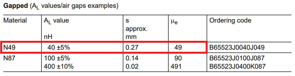
It has an $A_L$ factor of 40 nH. This means that the primary inductance is 40 nH × 15 turns × 15 turns = 9 μH. The primary magnetization current will peak at: -
$$\dfrac{V}{L}\cdot dt = di$$di is the change in current from 0 when dt is half the period of 400 kHz hence, di = 2.08 amps. This assumes that the applied primary voltage is a square wave of peak value 15 volts. It's really not clear from your question whether this is a million miles away from being true.
The H-field will 2.08 amps x 15 turns divided by the mean length of the core (in metres). This comes to 2,298 At/m. You have a core permeability (gapped) of 49 hence the peak flux density of this circuit will be: -
$$4\pi \times 10^{-7} \times 49 \times 2298 = 141 \text{ mT}$$Once you have this figure (a decent figure for a flyback circuit) you can begin to choose your wires but, it's highly unlikely that you will need Litz wire. For a resonant converter it's not a bad figure but, you might do better choosing an un-gapped core set and keep the magnetization current lower (due to significantly higher inductance for the same number of turns). I mean you have a peak primary current (no load) of 2.08 amps and the RMS will be root-3 lower at 1.2 amps. If the core was un-gapped, this figure would drop considerably (a good thing for an LLC series resonant converter).
1 comment thread

3 comment threads