PCB as a wall of an underwater enclosure
Can a circuit board be waterproof enough to form a wall of a waterproof enclosure?
Regular PCBs made of FR-4 with solder mask is what I have in mind. But I'm not barring less common PCB materials and processes, although I'd prefer something with moderate cost in moderate quantities.
10m depth in river and sea water.
Temperature range between +4°C and +40°C.
An ability to withstand freezing temperatures isn't required. But it's desirable, because that would let me field-test the device year round where I live.
Why would I want to expose a PCB to water? The malice aforethought is that the PCB has electrodes on the water side and a connector on the dry side. Here’s a rough and naïve sketch of what I have in mind.
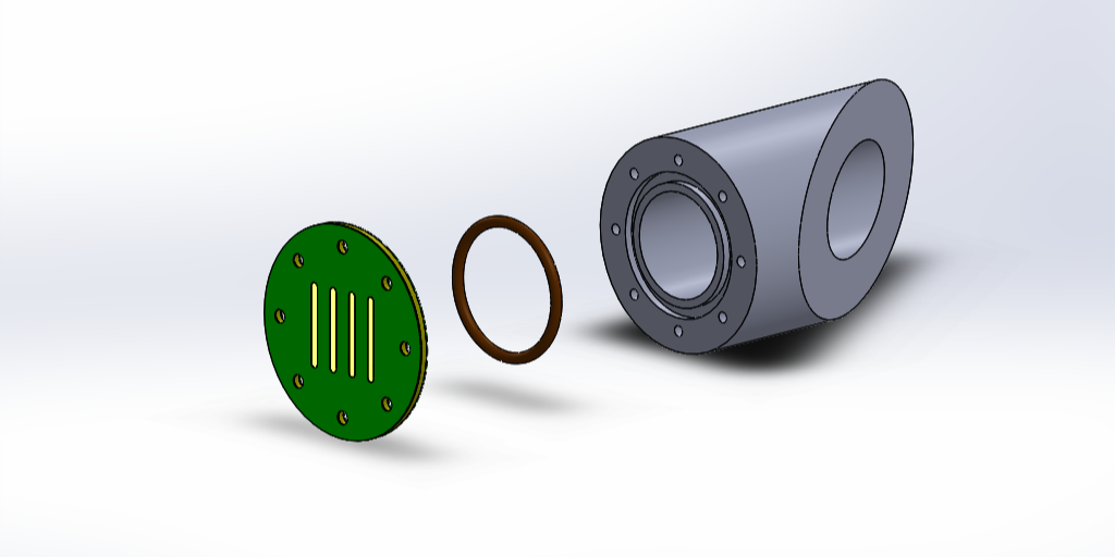
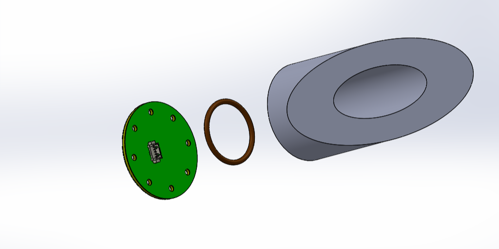
Solder mask overlaps the edges of the electrodes, and prevents water from getting under the electrodes.
Is ENIG plating enough to provide corrosion resistance for the exposed parts of the electrodes?
Vias are tented (or plugged, or via-in-pad, if necessary).
My findings so far:
I asked several PCB suppliers at a trade show about waterproofing PCBs, and one of them mentioned in passing that solder mask is waterproof. The common solder mask materials are epoxies (from what I read on the web), and epoxies can make good water resistant coatings. Two layers of solder mask, if coverage defects are a concern.
The wiki about FR-4 says that it has “near-zero water absorption”.
2 answers
You are accessing this answer with a direct link, so it's being shown above all other answers regardless of its score. You can return to the normal view.
I guess it would work.
I have used electrodes on a PCB to detect whether water level got high enough to turn on a sump pump. It worked, although it hasn't been installed very long. In that case the PCB extends upwards to where it is dry. That's where wires are soldered that go to the detection circuitry. The exposed parts of the electrodes are gold plated. I don't think there is anything else you can commonly get from a PCB process that would work.
I once worked on a product that had to detect whether it got immersed in a glass of drinking water. In that case, they used platinum-plated electrodes that were like thick and stiff wires coming out of the unit thru rubber grommets, so no PCB material was abused.
If I were doing this in a real product, I'd start with what you suggested, then try to do accelerated aging tests. I don't know what happens to soldermask after years of contact with water. It seems like it should be OK, but I'd test it before committing to volume production.
One thing I noticed with my one-off sump pump switch is that a film of crud gets deposited over anything immersed in the water for long. It doesn't hurt the electrodes, but I don't know if long term it might make it difficult to tell wet from dry due to the leakage. My particular water has a lot of iron in it.
One of my current investigations is sensing water level (not just present or not present) with a PCB, ultimately intended for a real product. I am uncomfortable with a direct electrical connection, so am using capacitive sense. Everything is covered by the soldermask. The one-off prototype is working very well, but I have no long-term reliability info.
You mentioned platinum-plated electrodes which dipped into drinking water. I noticed that high-end conductivity sensors use platinum electrodes (low-end sensors use stainless steel). I wonder why platinum? Is there something wrong with gold?
I don't know. I suspect two issues, process and durability. There is a well established process for applying gold coatings to PC board conductors. You can get gold-plated wire, but it's not common. We use gold-plated nichrome wire in some of our products, and it's a custom special order and not easy to arrange.
Gold seems better for contacts. I've tested gold/gold and gold/nichrome contacts. Even though nichrome is reasonably inert and it was clean, the electrical contact was less reliable at low contact force.
On the other had, I expect platinum to be more mechanically durable.
However, this is all speculation and the original answer stands: I don't know.
Even the best fiberglass and epoxy will suffer under certain conditions. Boat builders routinely test their mixes at varying temperatures and salinity levels. For the best knowledge for your use case, you will want to test the same kind of board under conditions designed to accelerate the deterioration of your part.
"Only exhaustive testing on finished parts can determine suitability for a particular application"
(I think that's from IP's Machinery Handbook, but I can't seem to find the quote right now.)

The circumference of your board (where it is cut into a circular shape in your picture) is a weak point: whatever coating you use (solder mask, epoxy resin, etc.) will likely begin delaminating at the edge between the face and the side, because the cut leaves a sharp edge, which produces a thinner coating right on the edge--coincidentally the same place where it will be more likely to be exposed to abrasion or exposed to other stresses and eventual damage. Then, since the ends of the fibers are exposed, the boards internal structure itself will be at risk of further delamination, since it is easier for water to "wick" into the board from the ends of the fiber than from the sides, rather like a wooden fence post sucks up water through its ends more than its sides. The bolt holes will be at a similar risk, but to a lesser degree.
You can improve this weak point by adding a structural bolt ring, or by giving special care to the protective coating by rounding the edges and sealing the edge of the board properly.
Another factor to consider will be varying pressure inside of your finished part, for example if it were a small capsule with some air inside; the pressure will vary with the temperature, causing flexing in the board which will also accelerate eventual structural failure. Not to poke fun at disasters, but "Remember the Titan!".
0 comment threads


5 comment threads