MAX485 transceivers breaking, Pi filter generating spikes?
Problem description & speculation about causes
I've having a problem with MAX485 transceivers breaking intermittently, passing our production tests but later failing. The error phenomenon is wrong signal voltage levels on the RS485 lines, as well as the transceiver failing to return the signals to 0V.
Switching out Maxim for another brand solves the problem. At first I suspected that we had gotten counterfeit parts, but that starts to seem less likely. Maxim/AD will give no technical support and are unhelpful in general.
What's notable is that we for some reason (still investigating why) is using MAX485 ESA instead of MAX485 EESA, the latter having built-in ESD protection diodes (which ought to be standard these days but apparently not). The other brands (TI, Sipex etc) that do not break have built-in protection diodes.
But since this design uses external TVS we never considered ESD a problem. The product has undergone ESD testing in a lab with 8kV contact 15kV air and passed. As well as a bunch of other very tough conducted/radiated susceptibility tests. So I'm pretty confident at ruling out ESD during production or product use as the culprit. We can also rule out external transients since some parts failed during production testing.
We have noted some spikes of a few volts extra on the edges of the RS-485 data. Nothing extreme - we probably dismissed it as poor scope ground or bad probes:
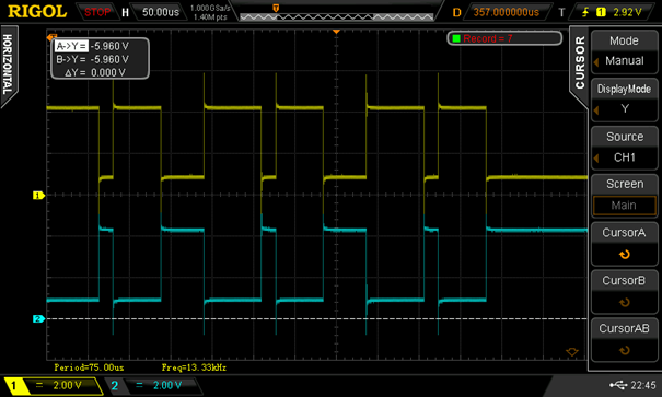
Baudrate is 50kbps.
What we suspect now is that a couple of extra Pi filters with ferrites (far right side of the schematic below), that were added late during a failed EMC test, could somehow create spikes through self-resonance(?) or some manner of EMF(?). Too low for the 33V TVS to kick in, but high enough to kill the MAX485.
Since switching to a 2nd source transceiver fixes the problem, the theory is that the protection diodes of the 2nd source part takes care of these small spikes.
Schematic
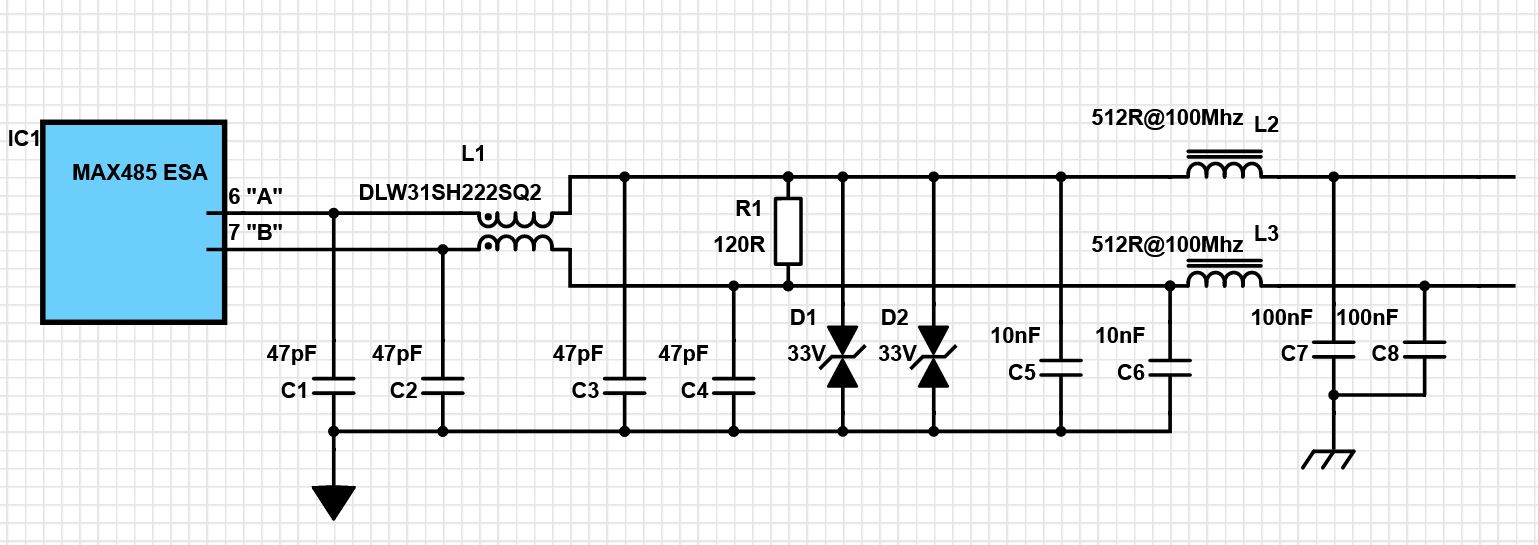
EDIT: D1 and D2 are on different lines, naturally. I messed up while redrawing the schematic.
Datasheets/BoM:
- IC1 MAX 485
- L1 common mode choke
- L2, L3 ferrite beads
- D1, D2 Bidirectional TVS 33V 600W peak pulse
- C1 to C4 MLCC 0603 C0G 50V
- C5, C6 MLCC 1210 X7R 500V
- C7, C8 MLCC 1206 X7R 250V
- R1 1206 1%
Application description
The application is a 24VDC supply civil product for military use. It has gone through extensive EMC testing against MIL 461G and passed all tests (conducted/radiated emissions, conducted/radiated susceptibility, ESD, power supply tests etc etc). Since this includes a very broad range of noise from 2MHz up to 18GHz somewhere, all EMC counter measures are kept general-purpose.
We have 2x the above schematic that forms a point-to-point semi-duplex communication and either side of it is failing. As seen in the schematic, the outer caps of the Pi filter towards the connectors are chassis grounded. PCB ground is connected to chassis but not near the RS-485 lines.
Shielded cables are used and distances are approximately 30m. Baudrate 50kbps. We haven't used twisted pair, which would obviously be a sound idea, but passed EMC testing regardless.
The 47pF caps are for a bit of slope as well as filtering. The bus is terminated in both ends with 120R for 60R impedance.
Questions
- Are the theories about self-resonance or reverse EMF likely?
- Theories about something else be causing the problems?
- Might it be counterfeit parts after all? Even though we bought them from a reliable source (although not one of Maxim's favored ones). And this is such a common, well-known part - I've used it many times before in other projects.
- Any other design review concerns?
The problem is already solved in practice by blacklisting the Maxim parts as well as adding a few smaller TVS suitable for RS-485 signal levels. But I need to find the root cause.
2 answers
At first glance, your design looks reasonable. I assume D1 and D2 are really supposed to be on opposite data lines, and them both being on the A line is a typo?
One thing that sticks out to me is the value of the clamping diodes. Why so high? What's your expected common mode range? A large common mode range may be OK for receiving, but will cause trouble when sending anyway. RS-485 signals are supposed to be from 0 to 5 volts. Why not clamp with 6 V or so Zeners?
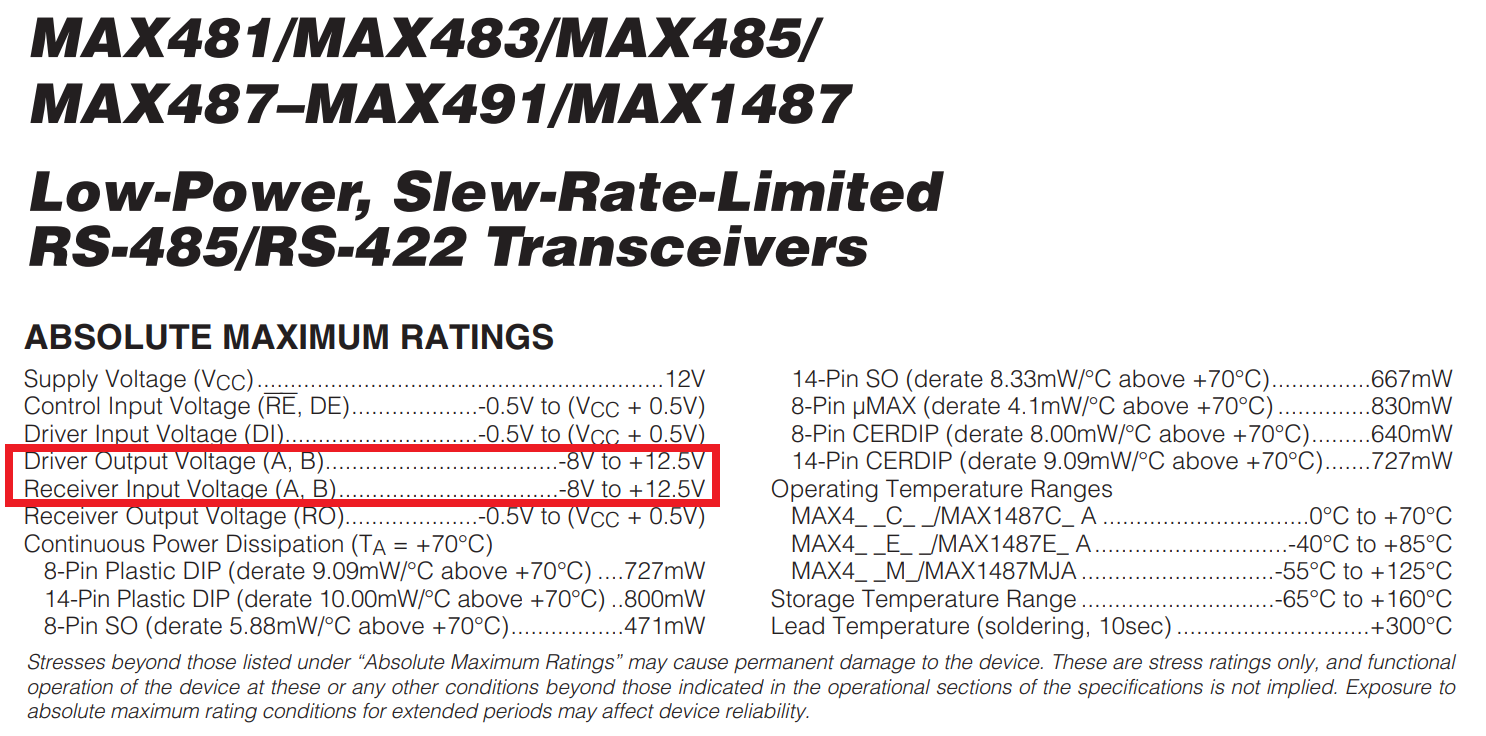
I just looked at the MAX485 datasheet, and it shows the absolute maximum Driver input voltage as only 500 mV beyond power at each end. This means it's not meant to handle a large common mode range anyway. I really don't get the 33 V clamps now. 5 V Zeners would make a lot more sense.
I vaguely remember a long time ago having issues with Maxim RS-232 parts. We ended up going with the TI version, which was pin-compatible. I remember the TI datasheet specifically pointing out the part's protection. Of course avoiding Maxim back then was necessary anyways for small volume purchasers. They were notorious for unavailable parts months on end unless you wanted to buy a few million.
I can't imagine why anyone would spec the unprotected part. What advantage does it provide? Pin protection circuitry isn't just for operation, although that's important for signals that go off-board like your RS-485. Pin protection also helps during production and general part handling. Proper ESD precautions are supposed to be followed, but stuff happens. One possibility is partial damage during production followed later by actual failure.
Your theory about ringing seems at least plausible. The ferrite chokes L2 and L3 are rated for 512 Ω at 100 MHz. That comes out to 815 nH, which is quite plausible for a small ferrite bead or chip inductor. 815 nH together with 10 nF has a resonance frequency of 1.8 MHz. That's well within the range of harmonics that could easily be on the line. That together with only 500 mV over and under voltage allowed on each line does sound like a bad match.
Put another way, this design is relying on the part clamping the signals to safe levels, but the chosen part specifically doesn't do the clamping. That makes no sense.
What part of the absolute maximum ratings for the A and B data lines do you think would be protected by 33 volt TVS diodes: -
If the chip is powered from a 5 volt supply then you use 5.6 volt TVS diodes to ground. Maybe you can raise the TVS to 10 volt if you have a lot of common-mode noise on your your bus but, nothing else would cut the mustard. The 33 volt TVS diodes won't protect the chip.
Also watch out for GND loops from one part of your installation to another; significant currents can flow (I'm talking amps not mA) and this can do significant damage if not controlled. I've given up using non-isolated 485 chips for this very reason.

2 comment threads