Comments on Deriving resistor values for a taper pad attenuator
Parent
Deriving resistor values for a taper pad attenuator
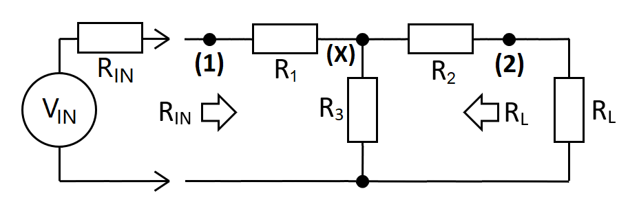
A taper pad is a resistive attenuator that maintains impedances on both ports and provides a specific amount of gain-loss ($A_{12}$): -
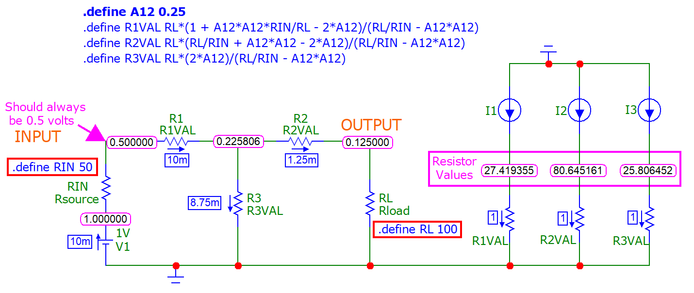
I have derived formulas for each resistor (that I know to be correct) and have checked with micro-cap using DC analysis: -
"So what" you might think. Well the problem is really that it took me ages to derive the formulas and, I am convinced that there must be a simpler approach than the method I took so, what I'm looking for is a shrewd and insightful way of finding (say) the value of R1 given: -
- The required gain-loss i.e. $\frac{V_2}{V_1}$ or $\frac{V_{OUT}}{V_{IN}}$
- The input impedance, $R_{IN}$
- The output load impedance, $R_{L}$
I don't want answers that say if you "do this" you can "find that" then it's easy to drill-down to what you want. I want to see the actual math. I've done it (and my algebra is correct) but, it was very long-winded and I'm sure I missed a trick along the way.
I will also add one more important thing that I've come to realize: none of the existing calculators out there (apart from mine) get the formulas correct. They show correct formulas for equal input and output impedance but, they screw up when the input and output impedances are different.
Post
The following users marked this post as Works for me:
| User | Comment | Date |
|---|---|---|
| Andy aka | (no comment) | Oct 13, 2022 at 17:23 |
Yeah, that looks like it's going to be messy.
I agree with Olin: the problem starts with three variables and three conditions so, no matter how you look at it, you will end up with a system of equations.
However, you can take certain shortcuts (using your 1st picture):
$$\begin{align} R_{23}&=R_3||(R_2+R_o) \tag{1} \\ R_{13}&=R_3||(R_1+R_i) \tag{2} \\ R_i&=R_1+R_{23} \tag{3} \\ R_o&=R_2+R_{13} \tag{4} \end{align}$$
[edit]
[edit 2]
$R_{23}$ is the resistance at point X with the input disconnected, and $R_{13}$ is the rsistance at point X with the output disconnected.
Then, the input source always sees its $R_i$ in series with the equivalent $R_i$, while the output voltage is always $\frac{A}2$ over $R_o||R_o^{eq}$ ($A$ is the attenuation relative to a unity input). Thus:
$$\begin{align} I_1&=\dfrac{1}{2R_i} \tag{5} \\ I_2&=\dfrac{A}{2R_o} \tag{6} \\ I_3&=I_1-I_2=\dfrac12\left(\dfrac{1}{R_i}-\dfrac{A}{R_o}\right) \tag{7} \end{align}$$
Since the biggest unknown is $V_x$, calculate it with (3) in mind:
$$V_x=\dfrac12\dfrac{R_{23}}{R_{23}+R_1}=\dfrac12\dfrac{R_i-R_1}{R_i-R_1+R_1}=\dfrac12\dfrac{R_i-R_1}{R_i}=\dfrac12\left(1-\dfrac{R_1}{R_i}\right) \tag{8}$$
Now calculate $R_2$ and $R_3$ based on (6), (7), and (8), while considering that $V_1=\frac12$ and $V_2=\frac{A}{2}$:
$$\begin{align} R_2&=\dfrac{V_x-V_2}{I_2}=\left(\dfrac{2V_x}{A}-1\right)R_o=\left(\dfrac{1-\dfrac{R_1}{R_i}}{A}-1\right)R_o=\dfrac{\big((1-A)R_i-R_1\big)R_o}{AR_i} \tag{9} \\ R_3&=\dfrac{V_1-V_x}{I_1}=\dfrac{2V_xR_iR_o}{R_o-AR_i}=\dfrac{\left(1-\dfrac{R_1}{R_i}\right)R_iR_o}{R_o-AR_i}=\dfrac{(R_i-R_1)R_o}{R_o-AR_i} \tag{10} \end{align}$$
Since $R_i$, $A$, and $R_o$ are given, both (9) and (10) are dependent on $R_1$, only. Now, use (2) and (4) to derive the expression for $R_1$:
$$R_o\stackrel{(2,4)}{=}R_2+\dfrac{(R_1+R_i)R_3}{R_1+R_3+R_i} \tag{11}$$
After expanding and collecting the terms:
$$R_1=\dfrac{(R_o-R_2)R_i-(R_2+R_i-R_o)R_3}{R_2+R_3-R_o} \tag{12}$$
Substituting (9) and (10) in (12) takes a few lines of simplifications to give:
$$R_1=\dfrac{R_i^2\big(A^2-(2A-1)R_o\big)}{R_o-A^2R_i} \tag{I}$$
At this point, if you want to keep things simple(-ish) then use $(\text{I})$ for $R_1$ and then, sequentially, calculate (9) and (10) through substitution. Otherwise, you'll need a few more lines of simplifications to give:
$$\begin{align}
R_2&=\dfrac{R_o^2+(A^2-2A)R_iR_o}{R_o-A^2R_i} \tag{II} \\
R_3&=\dfrac{2AR_iR_o}{R_o-A^2R_i} \tag{III} \
\end{align}$$
I find it interesting that all of them are divided by $R_o-A^2R_i$. Maybe there is something to it, hopefully a simplification but, now, my eyes are getting crossed by the amount of MathJax so, I'll take a break. I'll double check later on but, for now, it looks like I haven't made any mistakes.
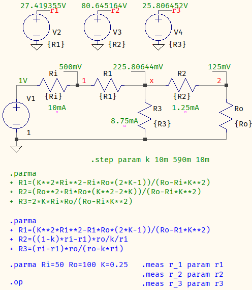
A SPICE test with your values confirms both approaches (blue text is active, upper sources output the resistor values, k means $A$):
[edit 3]
This is mostly cosmetic, it certainly doesn't reduce the derivation (it actually adds to it) but, inspired by the formulas from this site (which do not account for correct attenuation), $R_3$ can be calculated as in ($\text{III}$) and then $R_1$ and $R_2$ calculated from (3) and (4), based on it, resulting in slightly more palatable equations:
$$\begin{align} R_1&=\sqrt{\dfrac{\bbox[5px,border:black solid 1px]{R_i}}{R_o}}\sqrt{R_iR_o+R_3^2}-R_3 \tag{IV} \\ R_2&=\sqrt{\dfrac{R_o}{\bbox[5px,border:black solid 1px]{R_i}}}\sqrt{R_iR_o+R_3^2}-R_3 \tag{V} \end{align}$$

1 comment thread