Comments on Confusion in operation of analog computer
Parent
Confusion in operation of analog computer
I am studying for a test in control systems and we have a practical part which is to program a analog computer.
Here is a picture of the analog computer:
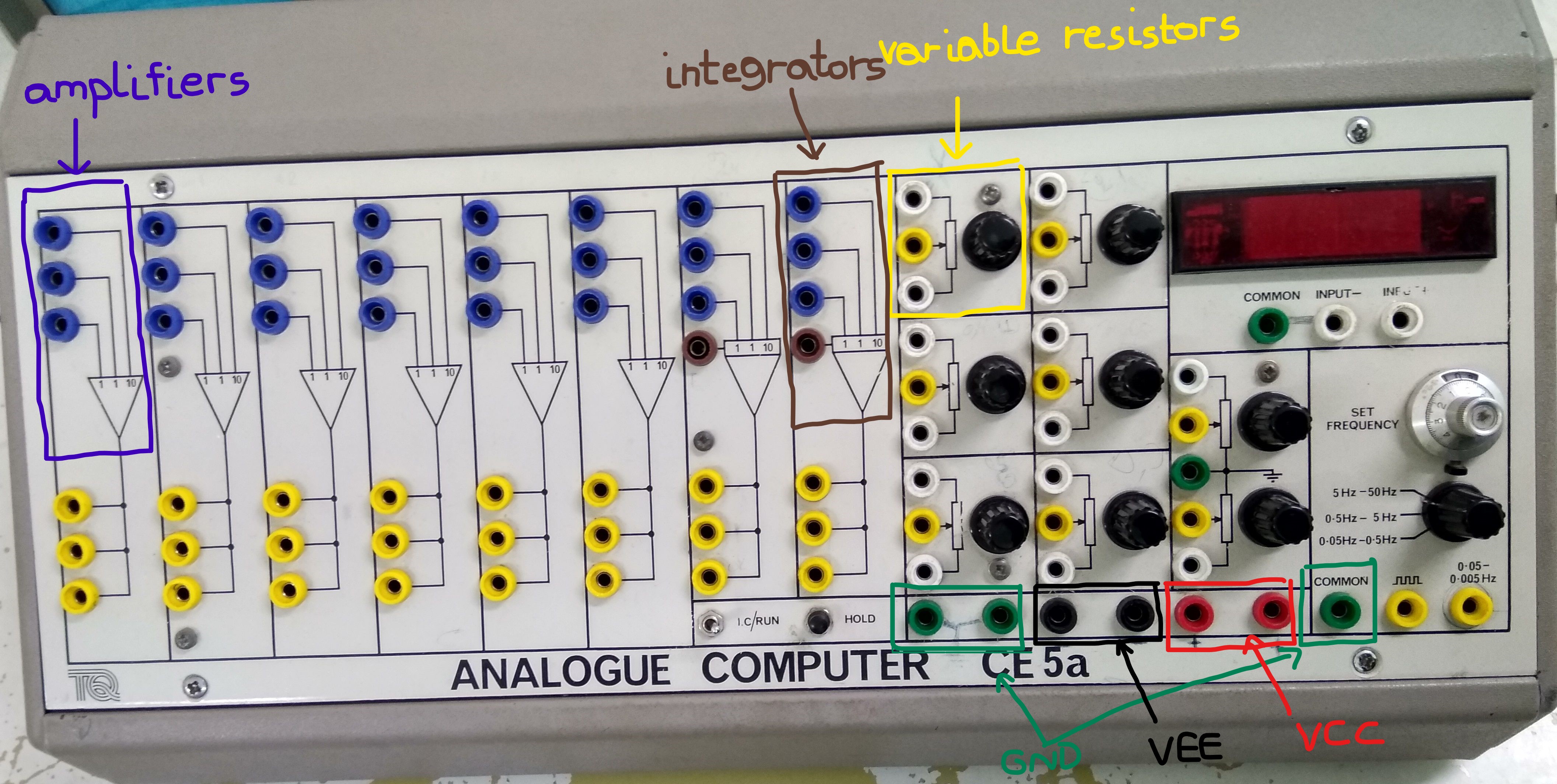
The variable resistor is basically a voltage divider between VCC and VEE and you can change the output voltage by changing the position of the potentiometer.
Suppose we have this block diagram
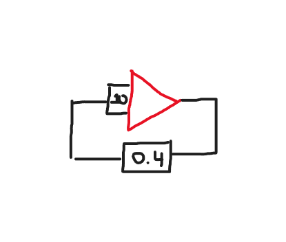
We set the potentiometer to multiply the signal it sees by 0.4 then return to the input of a amplifier.Next to the potentiometer there are 3 pins the top pin and bottom pin are connected internally to VCC and VEE and the middle pin is the voltage division.When we are done setting the value of the potentiometer and connect the middle pin to the input of a amplifier and we are ready to measure the output voltage with a oscilloscope do we still keep the top and bottom pins plugged to power or not?Will I create a short if I keep the top and bottom pins plugged to power?
Post
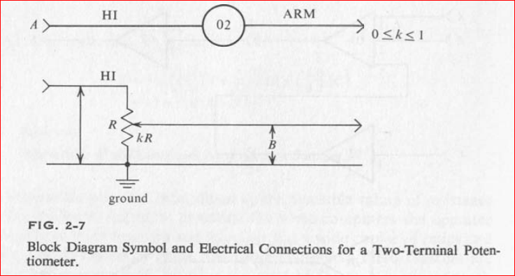
The two-terminal symbol for the attenuator comes from 3 pin potentiometer (pot.) referenced to 0V = "GND"
The summing amplifier is always inverting and gives you 3 options for gain which means internally it uses a 3 pin pot. to choose the gain for you based on the ratio of resistance from output to input side.
So when you choose an input like 10, does it make sense to choose another gain input in parallel? (no). You do need to chose an input since your block diagram shows no other input.
Since you have no input (=0) to a gain input(=-10) and feedback of 0.4 , your output should be 0 * (-10) * 0.4 = 0
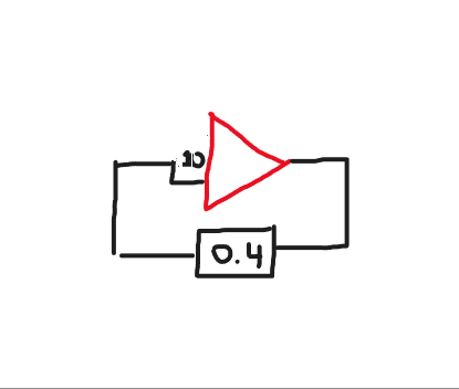
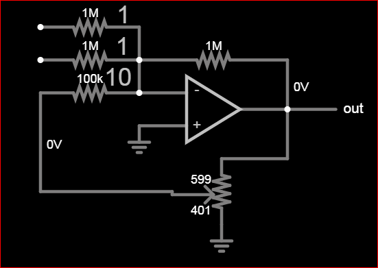
What you show looks something like this.
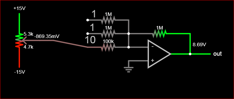
Since your question is also confusing without expectations or purpose, perhaps you are trying to take a ratio between Vcc and Vee and then connect that scope measured value to the inverting sum amp.
like this:

2 comment threads