Band pass filter given cutoff frequency and bandwidth
I have decided to try design a band-pass filter with a cut-off frequency of 10kHz and bandwidth of 2 Hz.
$$ \frac{1}{\sqrt{LC}} = 10001 \rightarrow LC = 1/100020001 sec^{2}$$
$$ \frac{R}{L} = 2Hz$$$$ \frac{1}{RC} = 2Hz$$Here is what I have done but if I plug the values to WolphramAlpha
it says it doesnt have any solutions.What am I doing wrong?
2 answers
I have decided to try design a band-pass filter with a cut-off frequency of 10kHz and bandwidth of 2 Hz.
- It's "10 kHz", not "10kHz". There needs to be a space between the number and the unit. NIST has a good document about this. Proper use of units and their presentation matter.
- I've said this before. Calling it a "cut off" frequency gives the wrong impression. One of your misconceptions in another question was based on not understanding there is a soft transition. "Rolloff" or "transition" frequency are much better names.
- A bandpass filter doesn't have a single rolloff or transition frequency. The ideal bandpass filter looks like a square pulse in frequency space. Of course that's not realizable, but the point is there are always 2 frequencies to specify for a bandpass filter. These are the low and high limits of the pass region.
- "Bandwidth" can be a spec for a bandpass filter. It is basically the difference between the two rolloff frequencies. However, both frequencies still need to be specified somehow. Put another way, there are two degrees of freedom in choosing frequency. Bandwidth only specifies one.
- No frequency spec for a filter means anything without a mention of how much attenuation there is at that frequency. For example, saying you want a 10 kHz to 20 kHz bandpass filter is meaningless without specifying the maximum attenuation allowed in that band. Sometimes -3 dB is implied for rolloff frequencies unless otherwise specified, but that is context dependent and not for beginners.
- Both the pass band and the stop band need to be specified. Saying you want a 10 kHz to 20 kHz bandpass filter with no more than 3 dB drop in the passband is a start. However, it doesn't say anything about what is supposed to happen outside the passband. Would you be happy with a filter that continues to only attenuate by 3 dB for all other frequencies? Probably not (even if that were realizable). You might say attenuation should be 20 dB per decade outside the passband. Or you could give a transition frequency range at either side of the passband, and specify the minimum attenuation outside the transition frequencies.
To put all this together, here is a sample spec for a bandpass filter:
Passband: 20 Hz - 20 kHz, gain within 0 dB to -3 dB.
Stopbands: 5 Hz and below, -20 dB maximum gain. 80 kHz and above, -20 dB maximum gain.
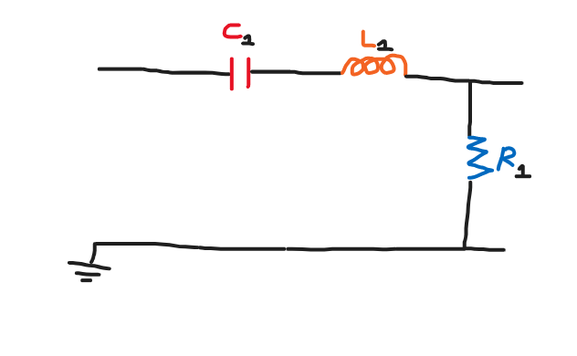
My mistake was taking the third relationship $$ \frac{1}{RC} $$ which says how to find the bandwidth of a parallel RLC filter but we have a series RLC filter.
Now solving the system : $$ LC = 100020001 , \frac{R}{L} = 2 $$
gives us the correct ratio between C1 and R1 and L1 with more detail:
C1:L1 = 100020001:1
C1:R1 = 100020001:2

4 comment threads