Activity for Volpina
| Type | On... | Excerpt | Status | Date |
|---|---|---|---|---|
| Comment | Post #288390 |
If the baud rate is very big then even small differences are very important. (more) |
— | almost 2 years ago |
| Edit | Post #288364 | Initial revision | — | almost 2 years ago |
| Question | — |
Synchronization of clock of satelite with devices here on the Earth Serial communication protocols require synchronization of the clock of the connected devices. From GR the time elapsed for the satelite is different than the time elapsed for us here on the Earth. So how can achieve synchronization of the clock of the satelite with our clock in order to for exampl... (more) |
— | almost 2 years ago |
| Edit | Post #288260 | Initial revision | — | almost 2 years ago |
| Question | — |
Understanding induction motors I have been watching this video and at 3:28 it says that a induction is inherently self-starting.Does this happen because of the energy stored and released in the windings of the statorFrom 3:41 until 4:40 it describes how the speed of the rotor oscillates between the speed of the stator and a spee... (more) |
— | almost 2 years ago |
| Edit | Post #288246 | Initial revision | — | almost 2 years ago |
| Question | — |
Contradiction between Routh's algorithm and checking with some value I am designing a control system controlled by some microcontroller K:  The open loop gain is $G{o}(s) = \frac{K}{s(s^{2}+4s+3)}$ and the closed loop gain is obviously $G{c}(s) = \frac{K}{s(s^{2}+4s+3)+K}$ I tried fin... (more) |
— | almost 2 years ago |
| Comment | Post #288233 |
@#58091 The output of a oscillator is AC by definition so I dont think a capacitor will help.I could be wrong tho. (more) |
— | almost 2 years ago |
| Edit | Post #288222 |
Post edited: |
— | almost 2 years ago |
| Comment | Post #288222 |
Unfortunately the CE5a is a very old machine and not very popular(it is mostly used for educational purposes).Sadly I didnt find its datasheet in the Internet. (more) |
— | almost 2 years ago |
| Comment | Post #288222 |
Ah i thought because you rotated it to change values is a rotary switch ,I have never seen a potentiometer in the form as shown in the picture. (more) |
— | almost 2 years ago |
| Comment | Post #288222 |
Well how do you call the switch which sets the output voltage of the variable resistor?Isnt that a rotary switch? (more) |
— | about 2 years ago |
| Comment | Post #288225 |
Yes you are correct that the output will always be 0 bcs I havent provided a input non-zero signal to my amplifier.So assume I apply a input square wave signal from a frequency generator and I apply it to the x10 multiplier pin then do I need to connect the top and bottom pins of the rotary switch t... (more) |
— | about 2 years ago |
| Edit | Post #288222 |
Post edited: |
— | about 2 years ago |
| Edit | Post #288222 | Initial revision | — | about 2 years ago |
| Question | — |
Confusion in operation of analog computer I am studying for a test in control systems and we have a practical part which is to program a analog computer. Here is a picture of the analog computer: Image alt text The variable resistor is basically a voltage divider between VCC and VEE and you can change the output voltage by changing ... (more) |
— | about 2 years ago |
| Comment | Post #288159 |
@#52987 I dont know thats why I am asking. (more) |
— | about 2 years ago |
| Edit | Post #288159 | Initial revision | — | about 2 years ago |
| Question | — |
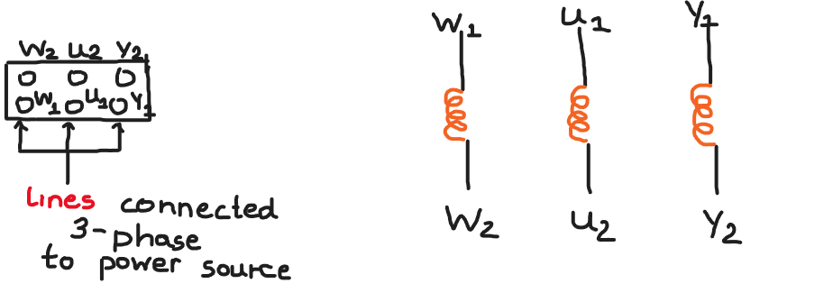
How is it possible to perform a open circuit test on a induction motor? During the open circuit test of a induction motor ,not any current flows inside the rotor.But how can we achieve such a thing? Here is the ping configuration of a induction motor:  The coils of the stator/rotor will be ... (more) |
— | about 2 years ago |
| Comment | Post #288153 |
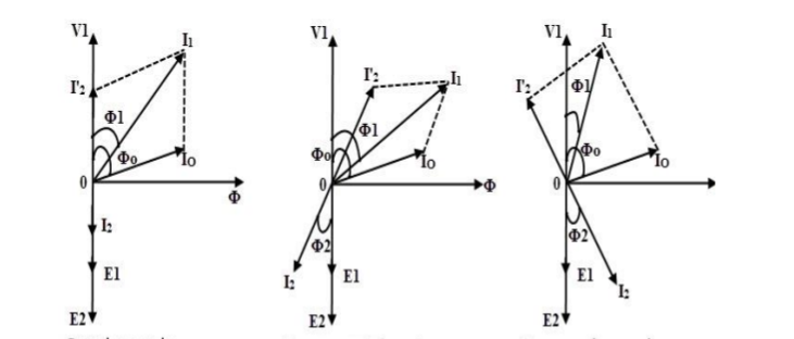
The image of the equivalent circuit of a transformer and the diagrams of the operation of a transformer under different loads dont come from the same source so the labels dont match.
A inductive or a capacitive load isnt a pure inductor or a pure capacitor its a combination of a series resistance wi... (more) |
— | about 2 years ago |
| Comment | Post #288153 |
Hmm there isnt a explanatory text around them ,the diagrams come from the slides of my college professor and he just showed us the diagrams without explaining what the quantities on the diagrams are.I am interested in knowing what they are. (more) |
— | about 2 years ago |
| Edit | Post #288153 | Initial revision | — | about 2 years ago |
| Question | — |
What are these transformer graphs about? This picture describes the behaviour of a single phase transform under resistive,inductive and capacitive loads(from left to right)  How what exactly is $V{1}$ ?Is it the voltage at the primary side?And what are $I^{'}{2}$... (more) |
— | about 2 years ago |
| Comment | Post #288118 |
The zener connected in the negative feedback loop regulates the voltage of the load anyway.I dont see the reason for that many zener diodes... (more) |
— | about 2 years ago |
| Edit | Post #288116 |
Post edited: |
— | about 2 years ago |
| Edit | Post #288116 |
Post edited: |
— | about 2 years ago |
| Edit | Post #288116 | Initial revision | — | about 2 years ago |
| Question | — |
Calculate values of externally excited DC generator/motor We use a DC externally excited generator/motor as a generator.We excite the input of the generator and get at the output 10V at 1Wb flux and at 5rps generator speed without connecting the generator to a load. Now we use the same DC externally excited generated/motor as a motor with 10V input volta... (more) |
— | about 2 years ago |
| Comment | Post #288107 |
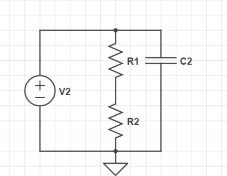
@Lundin My line of thinking was that by adding a big capacitor parallel to the DC voltage source , any noise current due to the thermal noise voltage of the resistors wont flow inside the voltage source which may damage it. (more) |
— | about 2 years ago |
| Edit | Post #288107 | Initial revision | — | about 2 years ago |
| Question | — |
Role of C2 (bypass capacitor) I have been reading about thermal noise in resistors and I have a question: Suppose we have this circuit:  Is C2 here to protect the voltage source from thermal noise?[]()[]() (more) |
— | about 2 years ago |


