How to protect RF switches from ESD?
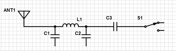
Assume that I have some generic antenna connector, followed by a pi-filter/50ohm impedance matching components, then a DC blocking cap (as per the RF switch recommendations) and then a RF switch for split tx/rx semiduplex transceiver, as in this schematic:
How do I best protect this RF switch from ESD coming in from human fingers touching the antenna connector? I need the highest ESD class (4) of the IEC61000−4−2, meaning 8kV contact discharge, 15kV air discharge.
I'm considering a specialized "ultra-low capacitance" TVS diode such as ESD8472 (rated up to 20kV), which is bidirectional.
Questions:
- Is this TVS diode the way to go?
- If so, where do I place it in this schematic? Directly on the antenna or somewhere else?
- How to determine the suitable breakdown voltage? I'm assuming it should be based on the RF switch supply which is 3.3V.
4 answers
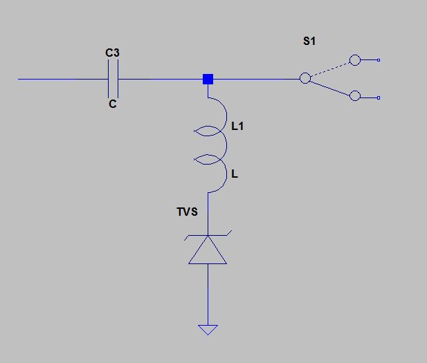
Those are good questions, and I don't have a single definitive answer for them. I'd start with putting an appropriate TVS (or maybe separate diodes to ground and 3.3 V) between C3 and S1. My reason for clipping there is because then this gets to work against the impedance of the inductor.
Look carefully at the capacitance of the TVS or diodes, and reduce C2 accordingly. This is where separate diodes might be necessary if you can't find a suitable TVS that has less capacitance than C2 needs to be.
In the end, you need to test yourself. Fortunately, the high voltage discharge models are usually no more than a capacitor and resistor, so you can make your own with a high voltage supply. Several places I've worked over the years made jigs like that. At HP we called it the "fickle finger" test. Testing it yourself lets you do fast turn arounds, and gives you confidence you'll pass the real test at the certification company.
It sounds as we will need to run this in a simulator or we'd be fumbling around in the dark
Seems the opposite to me. You need some real experimentation. There are too many unknowns to allow sufficiently realistic simulation of high voltage transients. There are parasitic capacitances all over the place. Parasitic inductances also matter. Capacitors can be quite non-linear at high voltages, and leakage in various places may not be resistive anymore either. The biggest unknown is how exactly the RF switch input reacts to short term out-of-range spikes.
All in all, this is a case where you need to use experience, intuition, and something called a "brain". Let the new kid play with the simulator while you actually fix the problem the old fashioned way by doing some real lab work.
Somewhat a pity to throw money for an expensive ultra-low capacitance TVS.
You have not specified what is the frequency range of your antenna system, but since you say you have to protect it from human fingers, it is likely to be a small antenna in the gigahertz range.
So, all what you need is a small, small, choke between C3 and S1, connected to ground via a stupid TVS, or even without TVS at all (since the the DC voltage between C3 and S1 is most probably at ground). Totally inexpensive.
Of course, you choose the inductor value to block 95% (say) of the lowest frequency in the given range and no more, which means a very small inductance at these frequencies. ESD discharges are much slower (in the MHz range at the worst), and after they have passed the pi filter, they will probably come much likely in the 100KHz range maximum. So, they will discharge to ground via the TVS, and hardly feel the small choke.
Note: many antennas, like the Vivaldi antenna or the self grounded bow tie antenna are made of a single block where the ground part is connected to the feeding part:
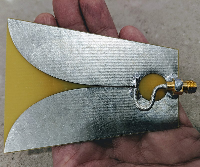
For those antennas, I believe it is pointless to protect the receiver from ESD.
In this case the antenna connector is the standard horrible little U.FL, which is connected with coaxial to a bigger one grounded to chassis. The main ESD risk is when someone is connecting or removing the coax. It's quite easy to touch the center pin with ones fingers on a U.FL. [from this comment by the O.P.]
Your vulnerable U.FL connector is inside the chassis. I'm assuming that only trained personnel will be working inside of your chassis (no user-serviceable parts, etc).
Put a note in the service manual that the person who unplugs the U.FL plug should wear ESD protection. Put ESD warning stickers inside the chassis too, for a good measure. I've seen this approach in medical devices.
[Edit. Just piling up reference material.]
SiLabs application note AN895. Fig. 19 shows an example for ESD protection circuit for a radio antenna port.
Currently there are $\boxed{\color{red}{\text{three}}}$ downvotes so maybe someone can explain why this has happened. Anyway, on to my downvoted answer: -
You have "mentioned" the threat (the ESD level) but, you haven't defined the peak voltage or current limit for the potential victim. Neither have you considered what the ESD pulse source impedance is and how the 8 kV is transformed to a significantly lower level by the capacitors in the pi filter.
Simulation is very effective in these situations but, you need to model the ESD source (there are a few different types) and, you have to choose the one that your device is expected to be able to cope with. So, here are the mitigations: -
- The ESD source (the threat) has output resistance and, it might be as low as a few hundred ohms or as high as 1.5 kΩ
- The first capacitor in the pi filter will slow down the ESD pulse and provide voltage limiting over the duration of the pulse
- The inductor and following capacitor may also have a beneficial effect or, may cause a nasty ringing voltage that might be worse than if they were not there. This is where simulation can help.
- The peak input current due to ESD into your "victim" might be several tens of mA and that may be good enough to win-the-day
But, without component values and ESD source impedance and details of the potential victim, it's guesswork. If the simulation shows that your victim may be over-stressed then there is absolutely no point hoping that your real circuit will survive the day.
You'll also need a discharge resistor for the pi filter if you are doing a series of ESD pulses because you don't want the charging voltage to form a staircase that progressively rises higher during the testing.
Bottom line: use a sim to get you to the point of deciding whether you need to add a TVS. Then choose the TVS and yes, it needs to be low capacitance to avoid detuning the pi filter but, there might be half a chance you won't need one.

2 comment threads