Results of analysis of Hartley oscillator dont make sense
I want to find the conditions of oscillation of the following Hartley oscillator.I have attached a load (ZL) to my Hartley oscillator
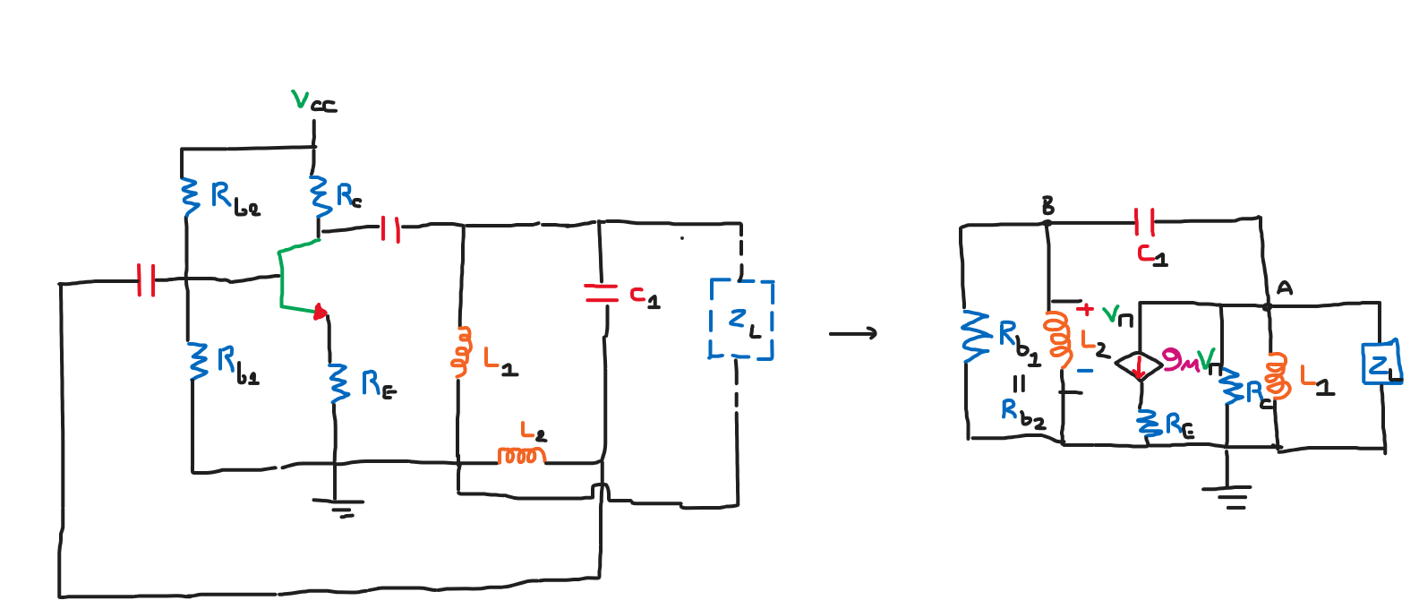
I have written KCL for nodes A,B:
For node A:
$$\frac{V_{A}}{sL_{1}} + \frac{V_{A}}{Z_{L}}+\frac{V_{A}}{R_{C}}-sC_{1}(V_{A}-V_{B})+g_{m}V_{x} = 0 \rightarrow V_{A}(Z_{L}R_{C}+sL_{1}R_{C}+sL_{1}Z_{L})-sC_{1}sL_{1}R_{C}Z_{L}(V_{B}-V_{A})+g_{m}V_{B} = 0 \rightarrow (g_{m}-sL_{1}sC_{1}R_{C}Z_{L})V_{B} = (-sL_{1}sC_{1}R_{C}Z_{L}-R_{C}Z_{L}-sL_{1}R_{C}-sL_{1}Z_{L})V_{A}$$
But $$\frac{V_{o}}{V_{in}} = 1 \rightarrow $$
$$g_{m}-sL_{1}sC_{1}R_{C}Z_{L} = -sL_{1}sC_{1}R_{C}Z_{L}-R_{C}Z_{L}-sL_{1}R_{C}-sL_{1}Z_{L} \rightarrow g_{m} = -R_{C}Z_{L} , -sL_{1}R_{C} = sL_{1}Z_{L} $$
which doesnt make any sense.Where am I doing wrong in my analysis?
3 answers
You are accessing this answer with a direct link, so it's being shown above all other answers regardless of its score. You can return to the normal view.
If you are pursuing engineering then you can't use doodles instead of schematics generated by dedicated (or not) programs. It will take you just the same amount of time, if not less, and the results would be clear for anyone seeing them.
The basic schematic of the Hartley oscillator can be simplified, for the purpose of analysis: the base resistors can be considered much larger than the input resistance of the transistor, so they can be eliminated, the coupling capacitors can be considered to give a sufficient bandwidth to not influence the response, so they can be shorted out, and the emitter and collector resistors, together with the load (resistance, not impedance, simplification for the sake of analysis) and internal resistance can be combined into one resistance. Now you can redraw the circuit like this:
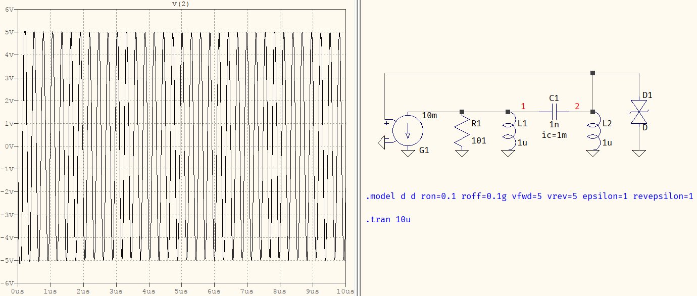
Given some small initial conditions, the circuit can be verified that it works. D1 is there to limit the amplitude, since the whole circuit would be linear, otherwise, and the oscillations would rise to infinity.
Note that $g_m$=0.01 and the load resistor is 101 Ω -- that is part of the necessary condition for the oscillations to start and be sustained (I'll show below). Here, the resistor is 101 Ω to compensate for the slight parasitics in inductors, capacitor, and the OFF resistance of the diode.
Now you can write down the equations Kirchhoff, out of which only one of them is of interest:
$$\begin{align} V_2\left(\dfrac{1}{sL}+sC\right)&=V_1sC \\ \Rightarrow\quad V_2&=V_1\dfrac{sC}{\dfrac{1}{sL}+sC} \\ \Rightarrow\quad V_2&=V_1\dfrac{s^2LC}{s^2LC+1} \tag{1} \end{align}$$
The energies at the output of the transistor and the input to the tank must satisfy:
$$\begin{align} (-g_mV_2)V_1t&\ge\dfrac{V_1^2}{R}t \tag{2} \\ (-g_mV_1\dfrac{s^2L_2C}{s^2L_2C+1})V_1t&\ge\dfrac{V_1^2}{R}t \\ -g_mV_1^2\dfrac{s^2L_2C}{s^2L_2C+1}t&\ge\dfrac{V_1^2}{R}t\quad\Biggr|_{\div V_1^2t} \\ \Rightarrow\quad -g_m\dfrac{s^2L_2C}{s^2L_2C+1}&\ge\dfrac{1}{R} \end{align}$$
At this point it's useful to eliminate the frequency by substituting $s^2=-\omega^2$, and using $\omega^2=1/[C(L_1+L_2)]$:
$$\begin{align} g_m\dfrac{\dfrac{L_2}{L_1+L_2}}{1-\dfrac{L_2}{L_1+L_2}}&\ge\dfrac1R \\ \Rightarrow\quad g_m\dfrac{L_2}{L_1}\ge\dfrac1R \tag{3} \end{align}$$
Which is the condition for oscillation. In your OP you wrote that the ratio of the output to the input voltage is 1, but it should be -1, since they're in anti-phase. If you want to include $Z_L$ in the equation, and the rest, feel free to do so, it will only add to the complexity, but this is the base of it.
(edit)
@LvW in the comments is right, so I'll make this mention: the resistive network for the polarization can influence the gain and, as such, the behaviour of the oscillations.
Here, the VCCS was set up as if having a fixed current gain (in a crude way), thus making possible to have an overall behaviour of a polarized transistor, while discarding the influence of the resistive network. In practice this cannot be done but, for the sake of a more clear result, that's why they were omitted.
MissMulan - at first, you should show which nodes are connected (crossing points). Secondly, where are the voltages Vo and Vin in your diagram? Please keep in mind, that it is essential to OPEN the feedback loop at a suitable point for injecting a test signal. Then, you can/must analyze the LOOP GAIN to verify the oscillation condition for a specific set of values.
More than that, it is recommended not to include an external additional load into your analysis.
0 comment threads
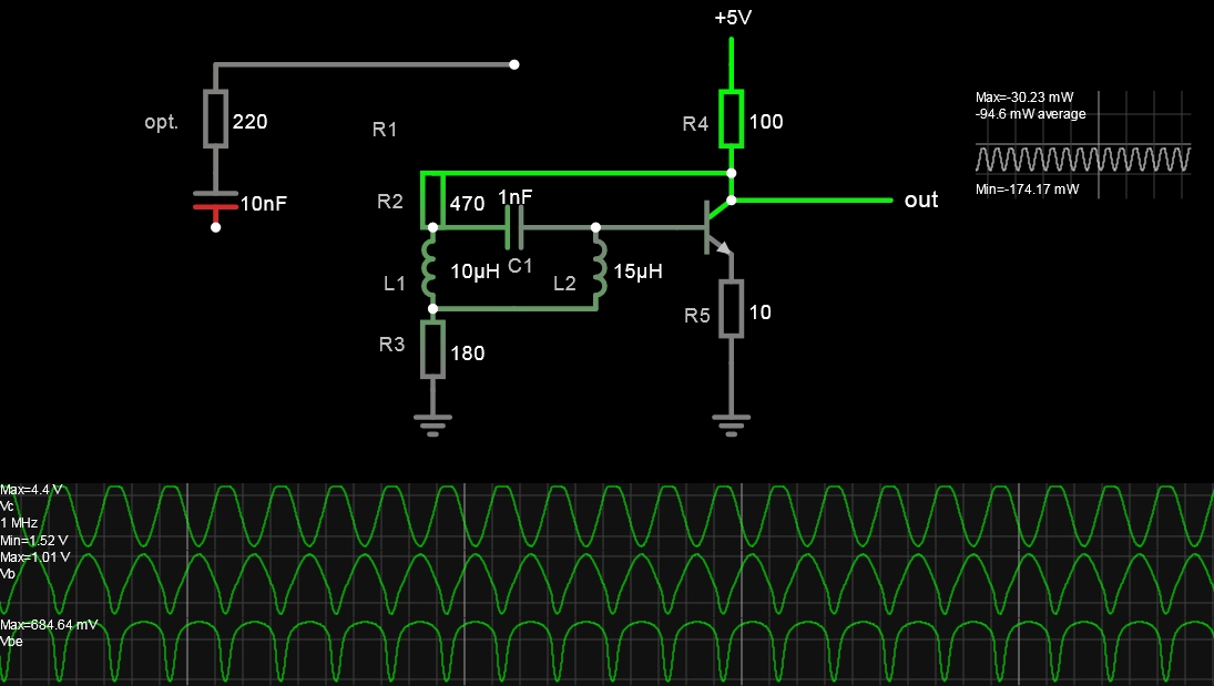
This LC circuit depends on several criteria for stable linear oscillation;
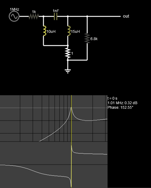
- 180 deg phase shift ( with 3rd order LC network) plus 180 degree inversion to achieve the oscillation criteria of 0 or 360 deg at gain >=1 Thus each reactance affects fo.
- adequate bias current and impedance ratios with negative feedback ratios at DC and at fo.
- Only 1 capacitor is necessary
A variation was made by adding the L1,L2 ground resistance for a notch filter effect.
- keeping the resistance ratios of R2/R3=1.5 to 3 range that affects feedback attenuation and impedance range used to satisfy requirements.
- The feedback cap. and H bias were also replaced with one feedback resistor, R2
- By tuning hFE to lower values, one can improve R ratios for sufficient gain to oscillate with pull up/down for a symmetrical sine wave.
- Excess gain will clip the sine wave.
The sensitivity to each resistance part value in the simulation gives more insight than the math and leads to a stable result. In reality, hFE is nonlinear with current, but I did add a slider for constant hFE = 10 to 50.
The highlight of this answer is to show the results of resistance ratios and hFE can be significant.
This design is not intended to be ideal, and there are better designs that have much higher Q for square wave clocks or nonlinear feedback for sine amplitude unity-gain AGC-like control.


0 comment threads