Activity for MissMulan
| Type | On... | Excerpt | Status | Date |
|---|---|---|---|---|
| Comment | Post #284018 |
They are not homework questions and I make the images on my own , it takes plenty of time in order to contribute to this site so please respect that. (more) |
— | over 3 years ago |
| Edit | Post #284021 | Initial revision | — | over 3 years ago |
| Question | — |
Inductance vs frequency Suppose we have a sine signal applied to a inductive load. Is the inductance of the load changed if the frequency of the signal is changed? (more) |
— | over 3 years ago |
| Edit | Post #284018 |
Post edited: |
— | over 3 years ago |
| Edit | Post #284017 |
Post edited: |
— | over 3 years ago |
| Edit | Post #284017 |
Post edited: |
— | over 3 years ago |
| Edit | Post #284018 | Initial revision | — | over 3 years ago |
| Answer | — |
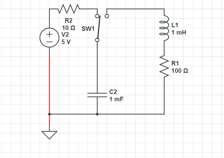
A: Series RLC circuit It all depends on the values of the components:If  the system will very slowly decay until the energy of the system reaches 0. If  the system und... (more) |
— | over 3 years ago |
| Edit | Post #284017 | Initial revision | — | over 3 years ago |
| Question | — |
Series RLC circuit How to find the equation of current of the RLC circuit after the switch is moved?  (more) |
— | over 3 years ago |
| Comment | Post #283960 |
@Andy aka if you read the answer a little bit below that statement (which is true) i say we have voltages due to mutual inductance-> we can say that a current exitting the doted end of the inductor can be translated to a voltage drop from the dotted end to the undotted end.
(more) |
— | over 3 years ago |
| Edit | Post #283958 |
Post edited: |
— | over 3 years ago |
| Comment | Post #283958 |
I mean how inductive coupling changes the total series inductance. (more) |
— | over 3 years ago |
| Edit | Post #283958 |
Post edited: |
— | over 3 years ago |
| Edit | Post #283960 |
Post edited: |
— | over 3 years ago |
| Edit | Post #283960 |
Post edited: |
— | over 3 years ago |
| Edit | Post #283958 |
Post edited: |
— | over 3 years ago |
| Edit | Post #283960 | Initial revision | — | over 3 years ago |
| Answer | — |
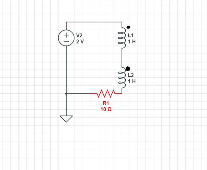
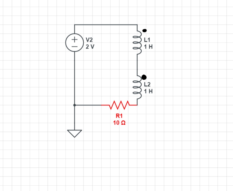
A: Coupling of inductors When 2 inductors share the same magnetic field they become coupled and besides their self inductance they have a mutual inductance as well. For this circuit:  Now current entering one coil marked with a dot, produces a ... (more) |
— | over 3 years ago |
| Edit | Post #283958 | Initial revision | — | over 3 years ago |
| Question | — |
Coupling of inductors Which will be the total series inductance?  (more) |
— | over 3 years ago |
| Comment | Post #283956 |
It isn't dimensionless im just doing the math. (more) |
— | over 3 years ago |
| Comment | Post #283956 |
I am using a LateX editor so I cant do what you want. (more) |
— | over 3 years ago |
| Comment | Post #283956 |
The (missing)units are obvious if you read the post. (more) |
— | over 3 years ago |
| Comment | Post #283956 |
I dont see any errors maybe you can enlighten me (more) |
— | over 3 years ago |
| Edit | Post #283927 |
Post edited: |
— | over 3 years ago |
| Edit | Post #283956 | Initial revision | — | over 3 years ago |
| Answer | — |
A: Voltage and Current of capacitor After the switch is closed: hi The general formula for finding the voltage of the capacitor is: hi where Vf is the voltage of the inductor after infinite time,Vo is the voltage of the capacitor at the time the switch is closed Because capacitors resist any change in voltage hi ... (more) |
— | over 3 years ago |
| Edit | Post #283955 | Initial revision | — | over 3 years ago |
| Question | — |
Voltage and Current of capacitor How do I find the voltage of the capacitor and the current through the capacitor after the switch is closed? (more) |
— | over 3 years ago |
| Comment | Post #283926 |
The circuit isnt wrong but what you have suggested is a improvement of the current source/switch relationship. (more) |
— | over 3 years ago |
| Comment | Post #283936 |
1) The current source provides 0.1A to the circuit but this could well have been a typo or you may have not seen it well which is partly my fault because I didnt write it brightly enough 2)the time costant is L1/R so the t/T must have units of Ohms*seconds/Henries (more) |
— | over 3 years ago |
| Comment | Post #283936 |
Olin maybe you may want to delete this post. (more) |
— | over 3 years ago |
| Comment | Post #283926 |
What do you mean by designators exactly!? (more) |
— | over 3 years ago |
| Edit | Post #283927 |
Post edited: |
— | over 3 years ago |
| Edit | Post #283927 | Initial revision | — | over 3 years ago |
| Answer | — |
A: Current and voltage of inductor After the switch is closed : hi The general formula for finding the current through the inductor is this: hi where If is the current through the inductor after infinite time,Io is the current of the inductor at the time the switch is closed. Because inductors resist any change in curre... (more) |
— | over 3 years ago |
| Edit | Post #283926 | Initial revision | — | over 3 years ago |
| Question | — |
Current and voltage of inductor How do I find the current through the inductor and the voltage of the inductor after the switch is closed? (more) |
— | over 3 years ago |
| Comment | Post #283904 |
Done check it out now. (more) |
— | over 3 years ago |
| Edit | Post #283904 |
Post edited: |
— | over 3 years ago |
| Comment | Post #283904 |
You are correct I will edit (more) |
— | over 3 years ago |
| Edit | Post #283904 |
Post edited: |
— | over 3 years ago |
| Edit | Post #283904 |
Post edited: |
— | over 3 years ago |
| Edit | Post #283904 | Initial revision | — | over 3 years ago |
| Answer | — |
A: Select resistor for a diode A diode obeys the Shockley diode equation and for this circuit we have:hi hi The current through the diode must not pass a limit so for LTL-307EE we go to the datasheet to find the maximum current before the diode is destroyed: For the LTL-307EE at 20C we have 10^4 A Isat and Vth=0.026V... (more) |
— | over 3 years ago |
| Edit | Post #283903 | Initial revision | — | over 3 years ago |
| Question | — |
Select resistor for a diode Suppose we have this circuit see me How do I pick a appropriate value for the resistor R1? (more) |
— | over 3 years ago |
| Edit | Post #283896 |
Post edited: |
— | over 3 years ago |
| Edit | Post #283896 | Initial revision | — | over 3 years ago |


